In this post we’ll get started with exploring Raspberry Pi GPIO pins. We’ll program the hello-world of GPIO programming: a blinking red LED. We’ll be using python as programming language. I am using a headless raspberry Pi zero wh with Raspbian Stretch Lite and I will talk to my headless Pi using ssh and transfer necessary files from my mac to Pi using scp commands. I am assuming you’ll have your Raspberry Pi up and running with Raspbian OS installed. If not then there are lot of articles on the internet describing how to setup your Pi and install Raspbian.
Things you’ll need:
- 1 * Raspberry Pi (I am using Pi zero wh model)
- 1 * bread board
- 1 * red LED light
- 1 * 330 ohm resistor
- 2 * female to male jumper cable
GPIO pins configuration
GPIO stands for General Purpose Input Output. With the help of GPIO pins a Raspberry Pi can connect and interact with external electronic components. Recent Raspberry pi models (Pi 3, Pi zero, Pi w and wh models, etc) contain 40 GPIO pin. Each pin can turn on or off, or go HIGH or LOW in electronic terms. If the pin is HIGH it outputs 3.3 volts, if the pin is LOW it is off.
 In our example we’ll be using the following two pins:
 pin 6 (ground) and pin 25. To know more about the GPIO pins in raspberry pi, checkout pinout.xyz.
Setting up the circuit
It is recommended to turn the Pi off while building the circuit. We’ll now create a circuit as depicted the the diagram below:
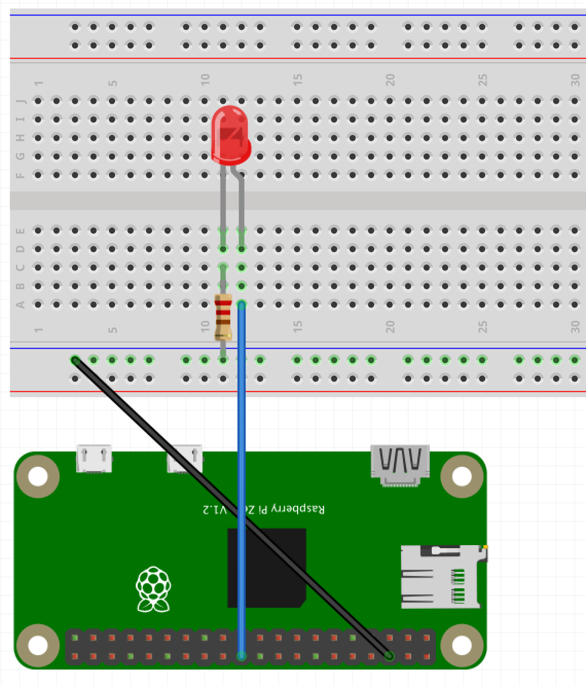 Note: The resistor in the image is of 220 ohm, but I have used 330 ohm in my circuit.
- Use a female to male jumper cable to connect
pin 6(Ground) (black cables, see the image above) to the breadboard negative row. - Use another female to male jumper to connect to connect GPIO pin no. 25 to point represented by row
Aand column12in the breadboard shown above. - Connect one end of a 330 ohm resistor to the negative row (corresponding to the black cable, highlighted in green) and connect the other end to the point represented by row
Ccolumn11in the breadboard as shown above. - The shorter end of LED is negative end and longer is the positive end. The longer end should always be connected to the point in the circuit with higher voltage (i.e. higher potential). The shorter end of LED is connected to a GPIO
pin 25(which can output 3.3V) via blue cable and longer end is connected to the groundpin 6(which is 0V and acts like the negative terminal of the battery) via black cable with resistor in between them.
Resistor
Keeping in mind that I had taken introductory classes on electrical and electronics engineering quite some time ago (4 to 5 years approx.), I had 2 questions that I needed answers for. Please bear with me for being naive in this context.
- Why do we need resistor in our circuit?
- How to determine what number of ohms of resistor should be used?
Resistor is required to dissipate the extra electrical energy (voltage) from Raspberry Pi. Raspberry Pi is rated to supply 50mA at 3.3V and lets say our red LED can have forward voltage of around 2V and consumes 4mA current. So the remaining 1.3V should be dissipated by the resistor. So by Ohm’s law, V = IR and hence R = (3.3V - 2V) / (4/1000) which comes to around 325 ohms and hence its recommended to use 330 ohm resistor.
Reference: Raspberry Pi forum discussion
Making the LED blink using python
Now that we have a complete circuit, next part is to program the GPIO ports to make the magic happen i.e. to get the LED to blink.
We will be using the output of GPIO pin 25 to make the LED blink. Start your Pi and in the terminal use the following command to install python library gpiozero. gpiozero library makes working with GPIO pins and connected external components very simple.
sudo apt-get install python3-gpiozero
Now we will run some python code. Save below code your your Pi file system in a file say blink1.py. The script basically turns on the LED connected to pin 25, sleeps to 1 second, then turns off the LED, again sleeps for 1 second. And this is done continuously until the program is terminated (pressing ctrl + c).
from gpiozero import LED
from time import sleep

led = LED(25)
while True:
    led.on()
    sleep(1)
    led.off()
    sleep(1)
Now from terminal go the the directory where the script is saved and run it using command: python3 blink1.py.
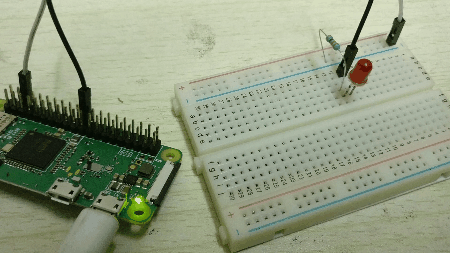
You will see the red LED blinking, like this:
We can build lots of fun stuff using gpiozero and similar setup. Check out the documentation page for gpiozero which demonstrates some interesting examples.
Try building a traffic light system.